What is P&ID?
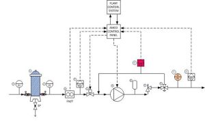
A piping and instrumentation diagram, or P&ID, shows the piping and related components of a physical process flow. It’s most commonly used in the engineering field.
Function and purpose of P&IDs
P&IDS are foundational to the maintenance and modification of the process that it graphically represents. At the design stage, the diagram also provides the basis for the development of system control schemes
For processing facilities, it’s a graphic representation of
- Key piping and instrument details
- Control and shutdown schemes
- Safety and regulatory requirements
- Basic start up and operational information
When to use P&IDs and who uses them
P&IDs are a schematic illustration of the functional relationship of piping, instrumentation and system equipment components used in the field of instrumentation and control or automation. They are typically created by engineers who are designing a manufacturing process for a physical plant.
P&IDs are used by field techs, engineers, and operators to better understand the process and how the instrumentation is interconnected. They can also be useful in training workers and contractors.
What are P&IDs all about?
P&IDs play an essential role in the process engineering world to show interconnectivity, but they don’t necessarily include specifications. Specifications are usually provided in separate documents. But they are incredibly useful in many ways, including:
- Evaluate construction processes
- Serve as a basis for control programming
- Develop guidelines and standards for facility operation
- Produce documents that explain how the process works
- Provide a common language for discussing plant operations
- Create and implement philosophies for safety and control
- Design a conceptual layout of a chemical or manufacturing plant
- Form recommendations for cost estimates, equipment design, and pipe design
What’s the difference between a process flow diagram (PFD) and a piping & instrumentation diagram (P&ID)?
Instrumentation detail varies with the degree of design complexity. Simplified or conceptual designs are called process flow diagrams (PFDs). A PFD shows fewer details than a P&ID and is usually the first step in the design process–more of a bird’s eye view. More fully developed piping and instrumentation diagrams (P&IDs) are shown in a P&ID.
A look at P&ID support documents
Because P&IDs are schematic overview graphics, you need documents to clarify the details and specifications. Here are some of them:
- Process flow drawings (PFDs). P&IDs originate from PFDs. A PFD is a picture of the separate steps of a process in sequential order. Elements that may be included are: sequence of actions, materials or services entering or leaving the process (inputs and outputs), decisions that must be made, people who become involved, time involved at each step and/or process measurements.
- Piping material specifications (PMS). Here’s where you find details about materials of construction, gaskets, bolts, fittings.
- Equipment and instrumentation specifications (EIS). Standards and details too extensive to fit into the P&ID are included in the EIS including Scope, Standards, Codes and Specifications, Definitions and Terminology, Materials of Construction, Design Basis, Mechanical/Fabrication, Guarantees, Testing and Inspection, Documentation and Shipping.
- Functional Requirement Specification (FRS). How the plant or system operates is detailed in the FRS. It includes the Functional Description, Communication, and Scope Definition of the process.
What should a P&ID include?
- Mechanical equipment with names and numbers
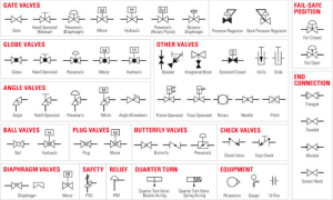
- All valves and their identifications
- Process piping, sizes and identification
- Miscellaneous – vents, drains, special fittings, sampling lines, reducers, increasers and swagers
- Permanent start-up and flush lines
- Flow directions
- Interconnections reference
- Control inputs and outputs, interlock
- Seismic category
- Interfaces for class changes
- Quality level
- Annunciation inputs
- Computer control system input
- Vendor and contractor interfaces
- Identification of components and subsystems delivered by others
- Intended physical sequence of the equipment
- Equipment rating or capacity
What should a P&ID not include?
- Instrument root valves
- Control relays
- Manual switches
- Primary instrument tubing and valves
- Pressure temperature and flow data
- Elbow, tees and similar standard fitting
- Extensive explanatory notes
How to create a P&ID
If you use software to create your P&IDs, there are some basic steps to follow:
- Create and check an equipment list. Use the symbols within the library after you’re sure of your list.
- Connect pipes and equipment, then review the details with a trusted colleague. Walk through the process several times and search for inefficiencies.
- Share with collaborators.
Organization fundamentals of P&ID
As a keystone document, the P&ID should be organized in a logical progression. While many—or most—companies set their own standards for P&ID organization, it can be thought of as chapters of a book or scenes from a movie that interconnect to tell your engineering process story. It should provide a concise and easy-to-understand illustration of all the equipment to be included in the process flow, alert information around hazard, safeguards and potential faults so that errors can be minimized or eliminated. It will help support the development of operating and maintenance procedures. As a storyboard of the process, it’s a way to see that changes can be made safely and effectively using Management of Change